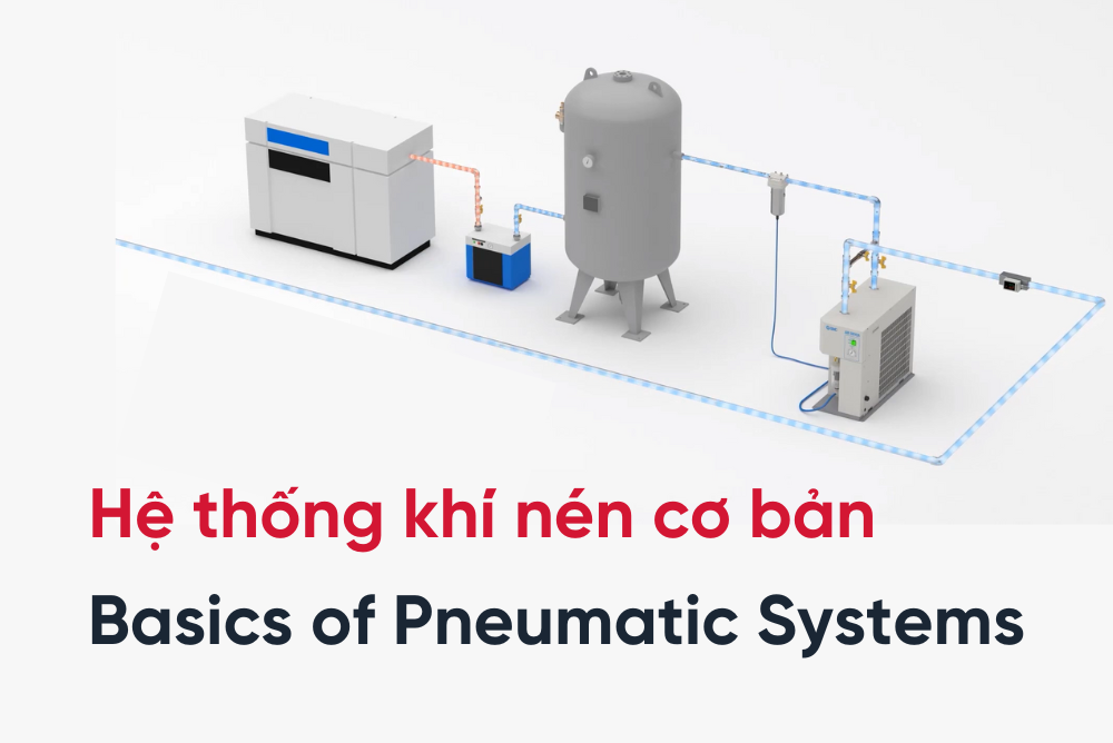
Pneumatic systems, or compressed air systems are used in a wide range of industrial and commercial applications. They are important because they offer a fast, efficient, and effective way to move and control mechanical devices. In this article, we will discuss the basics of pneumatic systems including how they work, their components, and applications.
What is a pneumatic system?
A pneumatic system is a mechanical system that uses compressed air to power mechanical devices. The air is compressed by a compressor and is stored in a tank. It is then distributed through pipes to various mechanical devices that use compressed air to perform work.
The standardized pneumatic system in a factory consists of the following components:
- Air compressor
- Aftercooler/Chiller
- Air tank
- Filters
- Air dryer
- High-precision filters
- Pneumatic tubes
- Auto drain valve
- F.R.L unit (Filter, Regulator, Lubricator)
- Pressure gauge
- Electric actuators
- Flow control valves
- Air cylinders
- Sensors

The standardized pneumatic system in a factory
All the components in the diagram are essential for the pneumatic system to work properly, and without them, it may not work efficiently or at all.
The diagram contains many pneumatic devices, which are divided into 4 groups: (1) Compressed air production equipment, (2) Compressed air cleaning equipment, (3) Compressed air transmission equipment, and (4) Compressed air consumption equipment.
I. Compressed air production equipment
The compressed air production equipment group consists of equipment such as an air compressor, a cooling system (aftercooler), and an air tank.
The air compressor draws in air from the surrounding environment and compresses it into high-pressure compressed air for use. After compression, the air will generate heat and pressure fluctuations, at which point it will be sent through the cooling system to lower its temperature (chillers/thermo-chillers/aftercoolers). The compressed air will then be directed to an air tank for storage and to stabilize the pressure fluctuation of the compressed air for subsequent phases.

Compressed air production equipment
1. Air compressor
An air compressor is the first equipment in a pneumatic system, which is responsible for drawing air from the environment, compressing it to high pressure, and then making it available for use. There are many different types of air compressors, but the two most common types are piston compressors and rotary-screw compressors.

Piston air compressors & Rotary-screw air compressors
Piston air compressors convert the rotary motion of an engine into the linear motion of a piston, which draws in air through an intake valve, compresses it, and then discharges it through a one-way valve. This type of compressor is typically used in systems that require air pressures of around 3 to 7 bar.
Rotary-screw air compressors operate on the principle of volume reduction, with two interlocking screws rotating at high speed to gradually decrease the volume in the compression chamber and generate compressed air. This type of compressor is typically used in systems that require air pressures of up to 10 bar.
When comparing the two types of compressors, rotary-screw compressors tend to produce more consistent flow rates and operate at lower noise levels, but have a higher initial investment cost than piston compressors. Therefore, rotary screw compressors are widely used in industrial settings, while piston compressors are commonly used in civil applications.
2. Chillers/ Aftercoolers:
After the air is compressed, it will generate heat and experience pressure fluctuations, at which point it will be passed through a cooling unit to reduce the temperature of the hot air.
The aftercooler unit is designed to cool the compressed air from temperatures of 80-100°C or higher down to approximately 40°C before use. 40°C is the ideal temperature, but in practice, the input temperature will determine the corresponding output temperature. Water vapor condenses during the cooling process and is discharged through an auto drain valve.
There are two types of cooling units: air-cooled aftercooler (HAA) and water-cooled aftercooler (HAW).

With the air-cooled aftercooler, the hot air is directed through the main pipeline and distributed through smaller pipes. A cooling fan blows ambient air through the smaller pipes and steel fins, which cools the compressed air to around 40°C. During the cooling process, some water will condense and is discharged through the auto drain valve.
Recommend when using an air-cooled aftercooler:
- Placing the air-cooled aftercooler in a well-ventilated location with good air circulation.
- At least 20cm away from walls or other machinery.
- If used in a dusty environment, a dust filter should be installed. Cooling pipes need to be cleaned regularly, and the automatic drain valve should be checked once a day.
With the water-cooled aftercooler, the hot compressed air flows into the input port and indirectly contacts the cooling water inside metal pipes, which lowers the temperature of the compressed air. The condensate water is discharged through the auto drain valve in automatic drain valve.
Recommend when using a water-cooled aftercooler:
- The factory must equip themselves with an additional air temperature controller.
- Ensure that the cooling water is clean and sufficient according to requirements
- Check the automatic drain valve once a day.
3. Air tank
Compressed air is further directed to the storage tank to stabilize the fluctuation of compressed air pressure.
The function of the air tank is not only to store compressed air but also to stabilize the fluctuation of the compressed air pressure. It is recommended to choose an air tank with a capacity of 6 to 10 times the volume of compressed air generated by the air compressor per second, which will help to ensure a stable output pressure. Additionally, it is essential to equip the tank with a safety valve, pressure gauge, and automatic drain valve.
There are two types of air tanks: large-capacity tanks (100-3000L) are typically used to supply compressed air for the entire plant, while small-capacity tanks (5-38L) are used to supply compressed air for a single line or machine. This type of tank also has a top base to combine with a pressure booster.

Air tank: AT series and VBAT series
The automatic drain valve has the function to automatically drain water based on the float mechanism. It is a device that is always present in the air compressor, aftercooler, air tank, and other equipment. The automatic drain valve is one of the solutions for draining water from the compressed air system.
II. Compressed air cleaning equipment
The compressed air cleaning equipment group consists of filters and an air dryer, with three primary filter levels: coarse filter, a fine filter, and ultra-fine filter to remove dirt, impurities, water, and rust from the compressed air system. The air dryer plays a crucial role in eliminating moisture from the compressed air. The coarse filter is placed before the air dryer, followed by the fine filter and the ultra-fine filter.


Why is it necessary to clean compressed air before use? If compressed air is not cleaned, it will contain a lot of dirt and impurities:
- Dust, impurities, and moisture are present in the compressed air due to it being taken from the outside air source.
- There is oil in the compressed air when it passes through the air compressor.
- The leading part of the compressed air transmission pipeline is typically metal, which can rust.
Therefore, a compressed air cleaning system, including filters with different levels and an air dryer, is necessary to provide clean compressed air for equipment and the downstream process.
The standard for compressed air is determined based on ISO 8573-1:2010
1. Filters
When passing through the filtration levels, compressed air will be filtered from dust, impurities, water, and oil.
The filters have the function of removing most of the dust, impurities, water, and oil from the compressed air system, improving the efficiency of the air dryer, prolonging its lifespan, and preventing incidents for the equipment in the pneumatic system. The filtration levels include coarse, fine, and ultra-fine filters. Coarse filters do not filter oil.

Air filters operate on a simple principle: compressed air enters the input port and flows into the filter core. Solid dust and impurities will adhere to the filter core and stay there depending on the filtration levels. Water and oil will accumulate at the bottom of the filter and be discharged regularly by the automatic drain valve.

When the output air pressure drops compared to the input air pressure at a determined level, the color indicator will be pushed up, making it easy for the operator to detect when to replace the filter core.

Time to replace the air filter core
When do you need to replace the air filter core? There are two cases:
- The filter core needs to be replaced once it has been used for two years
- When the air pressure drop at the output reaches 0.1 Mpa.
However, the operating time of each factory is different, so it depends on the maintenance conditions of the factory to flexibly choose the warranty time for the air filter that is suitable for their factory. In addition, SMC's air filter also has a color indicator to easily identify the time to replace the filter element. When the color indicator turns red, it is time to replace the filter element.
The following is the procedure for replacing the filter element:
- Use a hex key to remove the 4 screws on the top of the filter cover
- Rotate the filter body to separate it from the filter cover
- Remove the old filter element and replace it with a new one
- Assemble it in the reverse order of the filter removal process.
2. Air dryer
The air dryer is a device that removes water and moisture from pneumatic systems. Air dryers help improve the quality of the air supply, thereby meeting the operational requirements of machinery and equipment, and contributing to the productivity of the factory.
Depending on the system, environment, and different products, a suitable air dryer with a different principle and capacity can be chosen for use. Currently, we distribute three stable and reliable models of SMC air dryers on the market: refrigerated air dryers, membrane air dryers, and adsorption air dryers, all with different flow rates and dew points.

The refrigerated air dryer uses a closed cooling circulation system to condense steam into water and discharges it outside through an automatic drain. This type of air dryer has a large dry flow rate and a dew point in the range of 3-10°C, consuming minimal electricity and almost no compressed air during the drying process. The large-capacity refrigeration air dryer is usually placed in the compressed air room for source treatment.

The adsorption air dryer uses moisture-absorbent materials to remove moisture from the compressed air source. This type of air dryer has an output flow rate under 800 liters/minute, and a low dew point range from -30°C to -50°C. We provide one type of adsorption dryer that is heatless air dryer.

The membrane air dryer uses a special membrane layer containing hollow fibers inside to dry the compressed air by the pressure difference between the moist air inside and outside the membrane. This type of air dryer has the highest flow rate of up to 1000 liters/minute, with a very low dew point in the range of -15°C to -60°C.

Adsorption and membrane air dryers have negative dew points, making them ideal for applications that require high-quality air, such as in the food, pharmaceutical, and clean room industries, specifically used for CNC machines, measuring instruments, food processing machinery, packaging machines, semiconductor component manufacturing equipment, and electrostatic coating applications.
III. Compressed air transmission equipment

1. Pneumatic tube
The compressed air tube system consists of three types: metal tubes, rubber tubes, and plastic tubes.

- Metal tubes are typically used to connect equipment in the main compressed air room
- Rubber tubes connect the main line to subsidiary lines.
- Plastic tubes are used to connect equipment on the subsidiary lines.

Two types of pneumatic tubing systems
There are two types of pneumatic tubing systems in factories: straight and looped systems. Loop systems are more stable but have higher initial investment costs compared to straight systems.
When installing a compressed air pipeline distribution system in a factory, there are three important considerations:
- Every 100 meters of tube should have a drainage point to allow water to easily escape
- Automatic drain valves should be installed at the end of each line to drain water
- Gooseneck tubes should be installed where the main line connects to the subsidiary lines to prevent water from flowing back into the equipment.

2. Auto drain valve
The automatic drain valves are installed at the end of each production line used compressed air in the factory. The automatic drain valves have three types:

- The float type, which is simple and easy to operate with a low water discharge rate of about 100-400 cubic meters per cycle
- The electric type, which has a water discharge rate of more than 400 cubic meters per cycle
- The timer type, which is controlled by a recurring cycle of medium to high water discharge rates. When using this type, the discharge cycle can be set within a range of 0.5 to 45 minutes, and the water discharge time per cycle can be adjusted within a range of 0.5 to 10 seconds.

These are the positions of the automatic drain valves in the compressed air system of the factory, where the float-type automatic drain valve with low water discharge rate - AD series - is usually located at the end of the line or after the filter. The float-type automatic drain valve with medium water discharge rate - ADH series - and the electric automatic drain valve with medium water discharge rate - ADM series - along with the timer type automatic drain valve with medium to high water discharge rates are typically installed after the air compressor, air tanks, air dryer, and source-side filters.
IV. Compressed air consumption equipment
The compressed air consumption equipment group consists of three components in pneumatic systems: Modular F.R.L., valves as the control device, and pneumatic cylinder as the executing mechanism.

1. Modular F.R.L.
The modular F.R.L. is a combination of three devices: a filter unit (which filters out dirt, debris, rust from the piping, water and oil), a regulator (which adjusts the pressure to fit usage requirements and helps stabilize the oil output pressure), and a lubricator (which provides lubricating oil to the devices behind it).

The modular F.R.L. functions to remove dirt, debris, water, and stabilize the output pressure, and provide oil mists to the pneumatic devices behind it to operate smoothly. After the compressed air has been treated, it can be used by the machines, valves, and executing mechanisms. Depending on the type of production, each factory can choose to use different types of modular F.R.L.

- The modular F.R.L. combines the filter, the regulator, and the lubricator (AC).
- The modular F.R.L. has a filter integrated with the regulator, along with a lubricator, helping to save installation space (AC_A).
- Applications that require higher quality air also use fine filters in addition to coarse filters (AC_C, AC_D).
- For factories in the food, pharmaceuticals, or clean room industries that do not use oil, only the filter unit and the regulator are needed, or the integrated version of the filter unit and the regulator can be used (AC_B).
Let's explore each component in the modular F.R.L.:
The filter unit: Its primary function is to remove water and dirt particles from the compressed air system and filter out other airborne contaminants. It also filters out rust particles from the tube system, with a filtering efficiency of 5µm.
The regulating unit: Its function is to adjust and stabilize the output pressure to meet the requirements of the equipment and to minimize pressure fluctuations that can affect the operation of the machinery.
The lubricator: Its purpose is to provide lubrication for valves, cylinders, and other handheld compressed air tools. Most of the SMC devices that Temas supplies have been pre-lubricated with specialized grease and do not require additional lubrication.
2. Valves
A valve is a control device in a pneumatic system that controls the movement of compressed air in a pneumatic cylinder. In addition, it has other functions such as closing and opening air passages, releasing excess air, and blowing air.
A directional valve is a device that receives external signals (such as force, compressed air, or electromagnetic signals) to release, stop, or redirect compressed air flowing through it. In pneumatic systems, valves are often used to open and close air passages for various applications such as blowing air or controlling pneumatic cylinders depending on the specific needs of each application.
Directional valves are classified according to their operating method::
- Manual control: internal valves are operated using mechanisms such as buttons, pedals, or knobs. When the pressure stops, the valve returns to its original position with the help of a spring.
- Mechanical control: valves are operated by a mechanical linkage, a camshaft, or a roller that contacts a moving object.
- Electrical control: an electromagnetic coil creates a force that changes the state of the valve core.
- Pneumatic control: the valve operates by sending compressed air signals to the two ends of the valve core, causing the core to move.

Applications of various types of valves:
- Two-port valves: used to open and close air passages or for blowing air.
- Three-port valves: used to control one pneumatic cylinder or to open and close excess air passages in a pneumatic system.
- Five-port valves: used to control two pneumatic cylinders.

3. Pneumatic cylinders
Pneumatic cylinders are a mechanical device that converts the energy of compressed air into mechanical motion. This motion can be linear (push or pull), rotary (left or right), or gripping depending on the type of cylinder.
Some basic types of cylinders include linear cylinders, rotary cylinders, and gripping cylinders.

Pneumatic cylinders
Pneumatic cylinders are widely used in industries such as automotive, machinery, woodworking, and semiconductor, especially in safety and hygiene-related fields such as electronics assembly, food and pharmaceutical processing, and packaging on automated production lines. Additionally, cylinders are also used in other fields such as construction, transportation, mining, aviation, and more.
So, with Temas, you have learned about the basic pneumatic system in the factory. Temas provides SMC pneumatic equipment and other SMC factory equipment. Please send us your request via email to info@temas.vn.
Read more articles about industrial equipment here. Our product here.
- Source: SMC -
 Read more