 Contents
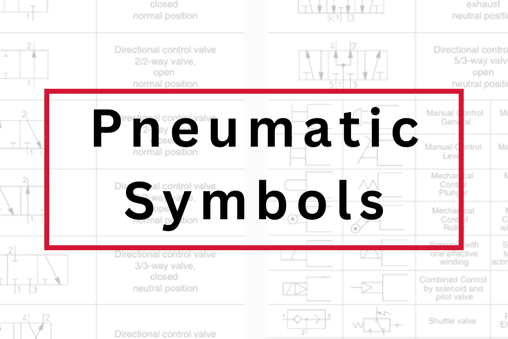
Pneumatic symbols come in many forms, each with its own meaning and function. Therefore, understanding each symbol in detail will help you grasp, design, and troubleshoot pneumatic systems with greater speed and accuracy.
This article will not go deep into explaining what a pneumatic system is. Instead, we will focus on the "visual language" behind these symbols. After reading, you’ll be able to recognize common symbols, interpret a basic pneumatic diagram, and keep a handy symbols guide for future use.
What Are Pneumatic Symbols?
Pneumatic symbols are standardized diagrammatic elements used to convey precise technical information. These symbols allow engineers to design, install, and troubleshoot pneumatic systems effectively.
In other words, pneumatic symbols act as the "visual language" of pneumatic systems. Instead of describing each component such as valves, cylinders, or filters in words, we use simplified, standardized geometric symbols to represent them. These symbols help engineers and technicians quickly understand the system’s structure and operation without lengthy explanations.

Basic Standard Diagram
Why Are Pneumatic Symbols Important?
Many people confuse a “block diagram” with a “standard pneumatic diagram.” A block diagram is a simplified schematic used mainly for teaching purposes, offering an overview of the airflow and functions from input to actuator. For example, the block diagram below helps you understand flow and function, but only at a high level.

Block Diagram
That’s why learning to read and use pneumatic symbols is so important—they are the technical language engineers use to communicate and ensure system safety and functionality.
One major advantage of using pneumatic symbols is the consistency they offer. Because they are standardized, everyone on the team—whether colleagues, suppliers, or different factories—can interpret the diagrams in the same way. Even when working with international partners who speak different languages, you can still collaborate and understand the same diagram.
Most pneumatic symbols follow ISO standards (e.g., ISO 1219), making them globally recognized. This consistency reduces design errors, shortens maintenance time, and prevents costly mistakes. Using standardized symbols in your diagrams enables others to easily troubleshoot, adjust, or expand the system without confusion.
Common Pneumatic Symbols and Their Meanings
Pneumatic systems include a wide range of components, and their symbols are equally varied. Understanding what each shape and arrow represents is the key to grasping how compressed air flows through the system. Let’s go through the most common pneumatic symbols with Temas and their meanings.
1. Directional Control Valves
Directional control valves are the foundation of most pneumatic circuits. Their symbols typically consist of adjacent square boxes containing arrows that indicate flow direction, along with ports showing air entry and exit. Symbol components include:
- Flow boxes: Each box represents one valve position
- Arrows: Indicate the direction of airflow
- Actuators: Show how the valve is actuated (manual, electric, pneumatic)
- Ports: Numbered connection points where air enters and exits

Directional Control Valve
Example: A 2/2 directional control valve (2 ports / 2 positions), normally closed.
2. Flow Control Valves
Also known as throttle valves, flow control valves regulate the speed and movement of compressed air. Symbol meanings:
- Arrow crossing a pipeline: Represents an adjustable orifice that controls airflow rate
- Check valve symbol: Allows air to pass in one direction and blocks reverse flow

Flow Control Valve
Throttle valves help control flow and stabilize movement, reducing pipe wear and playing a critical role in many pneumatic systems.
3. Actuators & Cylinders
Pneumatic cylinders, or actuators, provide linear or rotary motion and force in automated systems, such as those found in industrial machinery. Symbols typically use rectangles with diagonal arrows. Symbol meanings include:
- Diagonal arrow through piston: Indicates adjustable cushioning to reduce impact at end stroke—especially useful for high-speed or heavy-load applications.

Actuators & Cylinders
- Single-acting cylinder: Air pushes the piston in one direction, and a spring or external force returns it
- Double-acting cylinder: Air controls both directions of movement

Single-acting and Double-acting Cylinders (left to right)
4. FRLs – Filter, Regulator, Lubricator
The FRL unit conditions compressed air before it enters the pneumatic system. It removes contaminants like dust, rust, and water, thereby extending the life of downstream equipment such as valves, cylinders, and air tools. Symbol meanings (left to right):
- Air Filter: Removes impurities and moisture
- Pressure Regulator: Maintains system pressure. Represented by a square with a spring and arrow
- Lubricator: Adds a small amount of oil to reduce friction in downstream moving parts

FRL Unit
5. Ports and Flow Paths
Ports and flow paths are essential for receiving and distributing compressed air between components like valves, cylinders, and FRLs. They also guide and control airflow direction between ports. Symbol meanings:
- Port 1 (Supply): Inlet for compressed air
- Port 2 (Output): Outlet for compressed air
- Flow control valve: Arrow indicates adjustable airflow
- Check valve: Allows air to flow in one direction (from 1 to 2) and blocks reverse flow

Ports and Flow Paths
Mastering how to read and understand pneumatic symbols is a key factor in designing, installing, and maintaining pneumatic systems. These symbols are not just drawings—they are a technical language that enables engineers and technicians to work efficiently, reduce errors, and optimize processes.
From directional control valves and flow control valves to actuators and FRL units, each symbol plays a unique role in building a synchronized and precise system. A deep understanding of these symbols helps you quickly grasp the operating principles of the system while enhancing your troubleshooting and analytical skills.
We hope this article has provided you with a clear, intuitive, and practical overview of the most common pneumatic symbols. Don’t forget to save the Free Symbols Guide for convenient access. If you’d like to explore more about individual components or real-world diagrams, the Temas team is always here to support you.
| Download the Free Symbols Guide |
Reference: SMC Products

 Read more