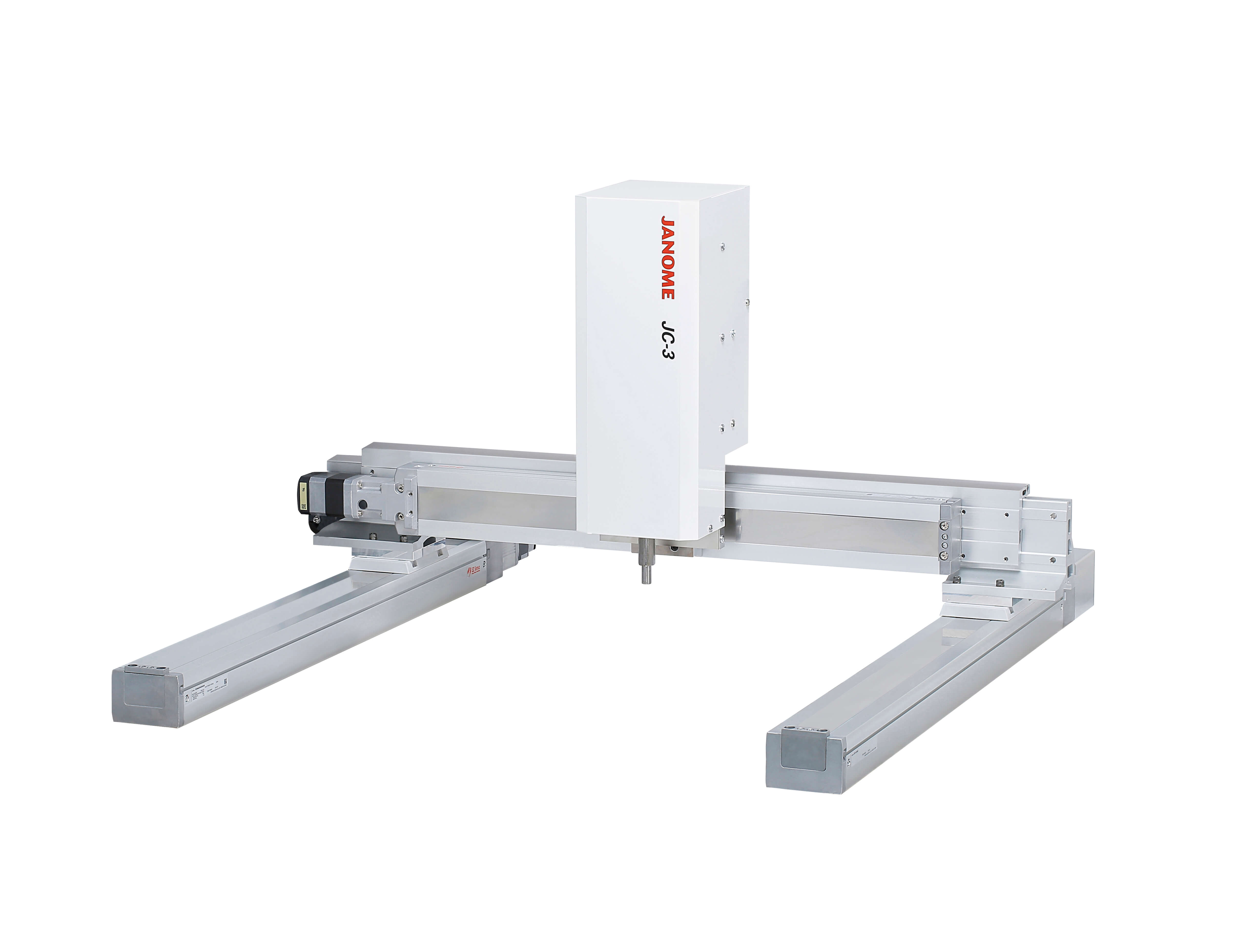
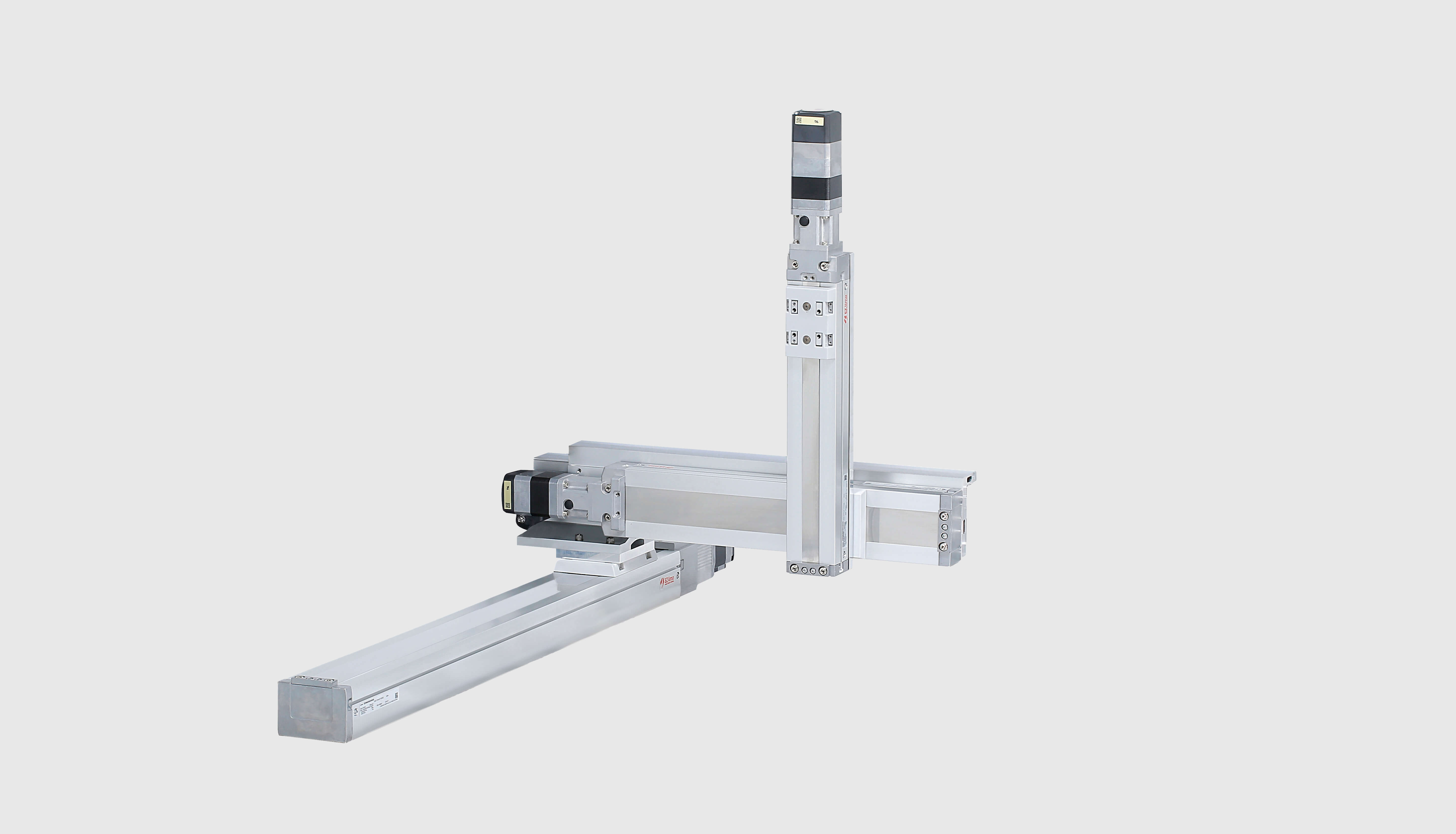
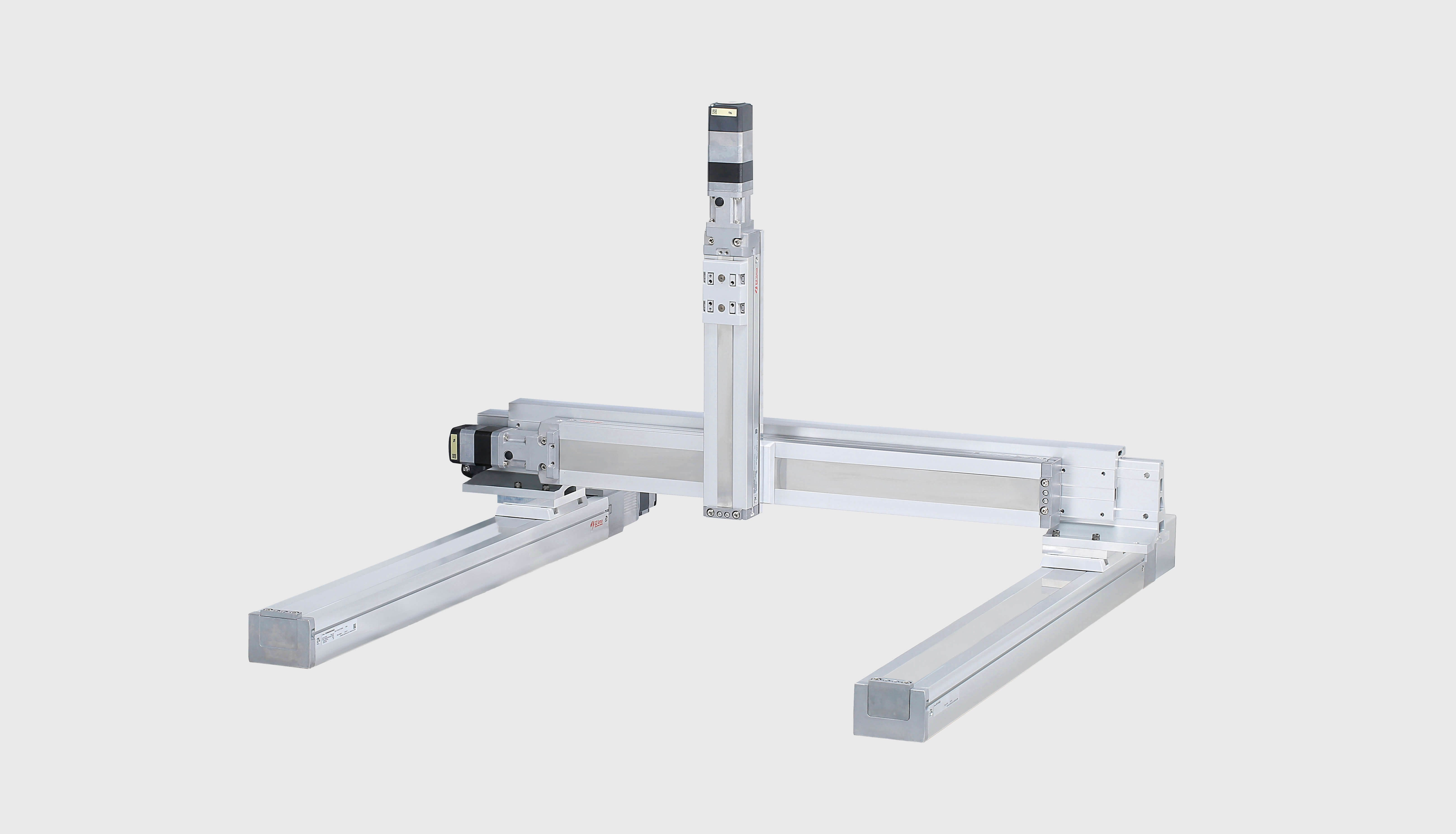
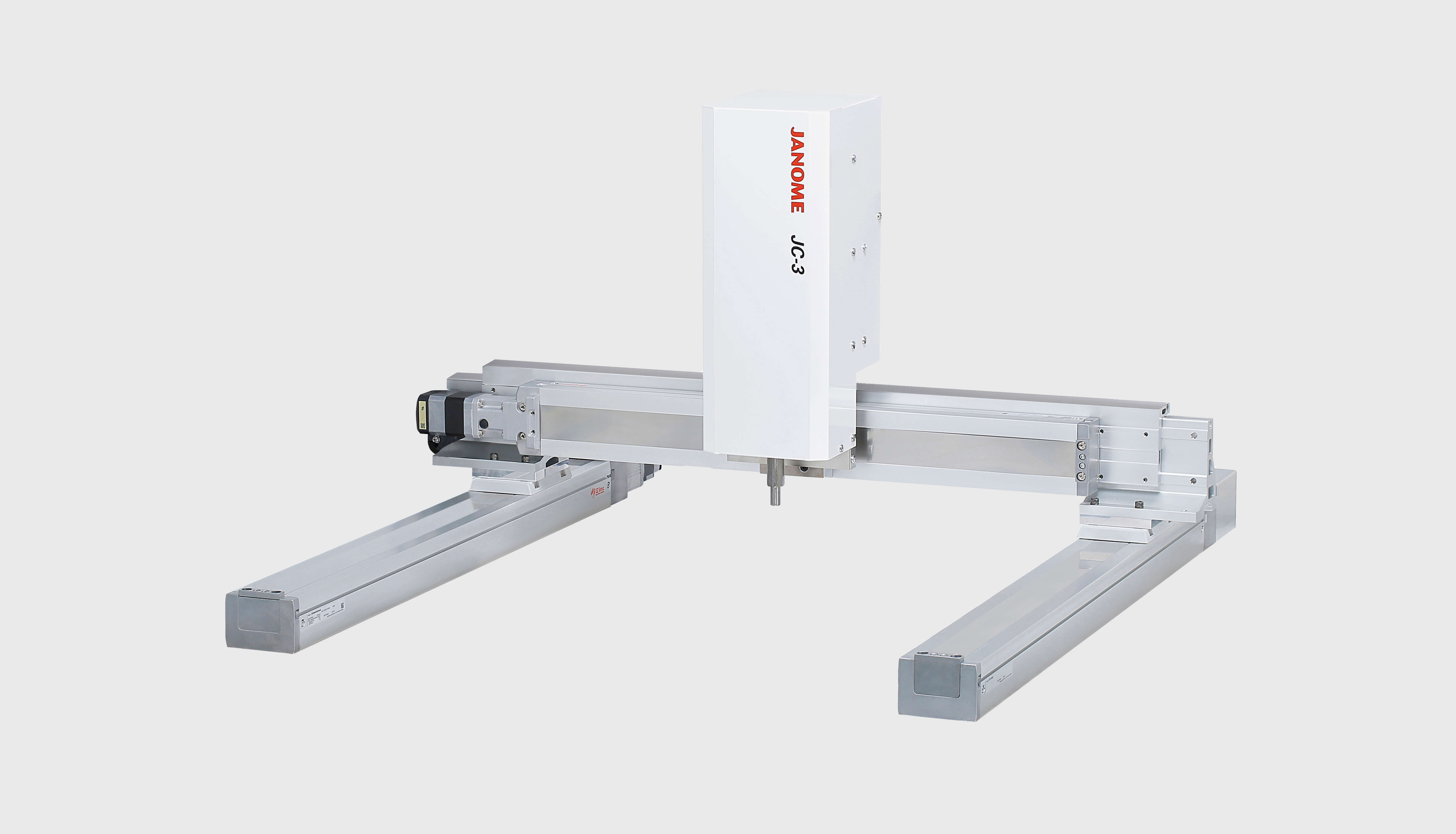
Multifunctional Cartesian robot with plenty of stroke combinations
Model: JC-3A00-0T3, JC-3A00-0H3, JC-3B01-0H4
| Model | JC-3A00-0T3 | JC-3A00-0H3 | JC-3B01-0H4 | ||||
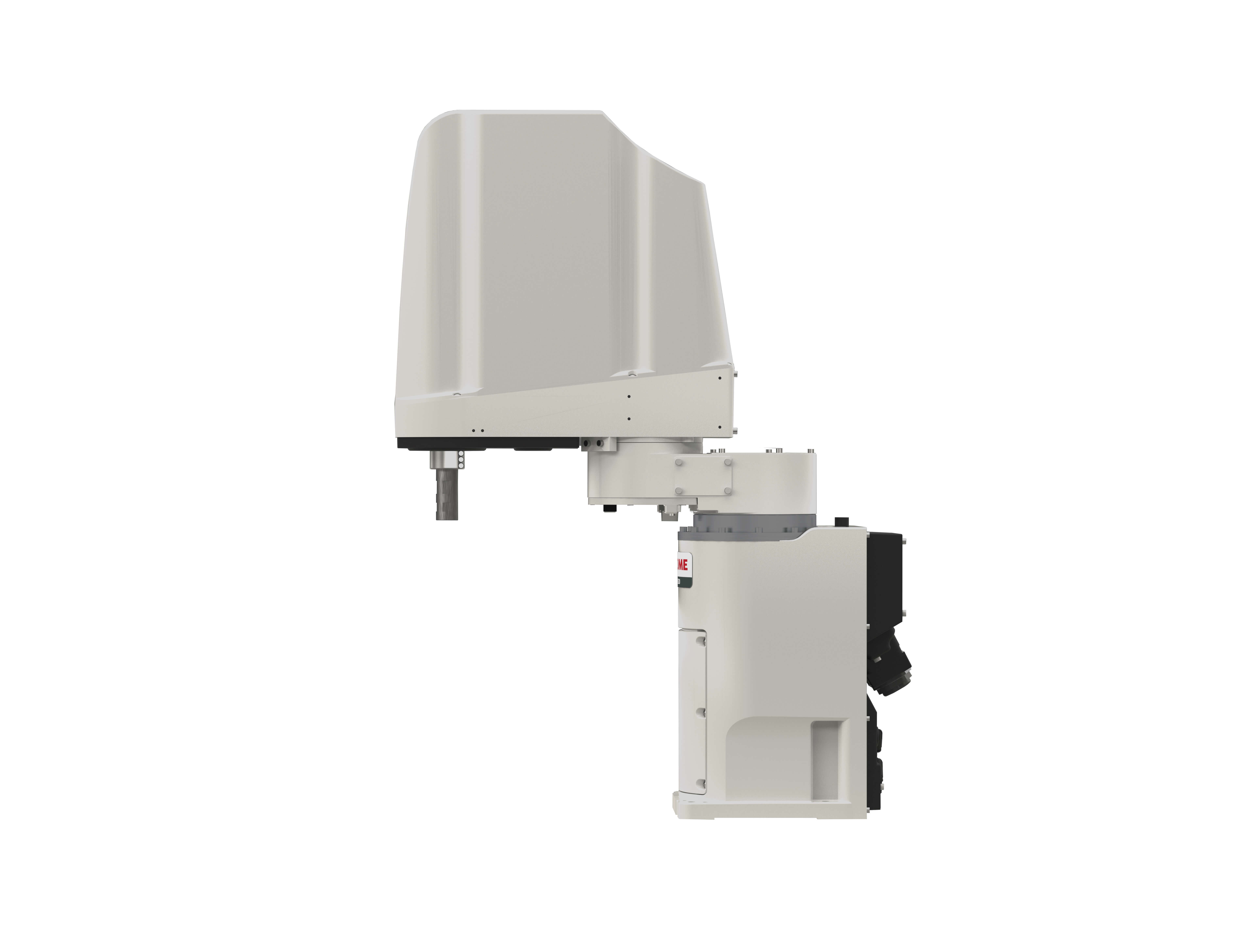
| Control Axes Directions | 3(XYZ) | 3(XYZ) | 4(XYZR) | ||||
| Stroke | X Axis(mm) | 200/300/400/500/600 | 300/400/500/600 | 300/400/500/600 | |||
| Y Axis(mm) | 200/300 | 200/300/400/500 | 200/300/400/500 | ||||
| Z Axis(mm) | 50/100/150/200 | 50/100/150/200/300 | 100/150 | ||||
| R Axis(deg) | - | - | ±360 | ||||
| Drive Motor | Stepping Motor | Stepping Motor | Stepping Motor | ||||
| X Axis | Feedback Control | Feedback Control | Feedback Control | ||||
| Y Axis | |||||||
| Z Axis | Open Loop Control | ||||||
| R Axis | - | - | |||||
| Maximum Portable Load |
Tool(kg) | 4 | 8 | 3 | |||
| Maximum Speed *1 |
X-Axis Stroke | 200 300 400 |
500 600 |
300 400 |
500 600 |
300 400 |
500 600 |
| X Axis(mm/s) | 700 | 800 | 700 | 800 | 700 | 800 | |
| Y Axis(mm/s) | 800 | 800 | 800 | ||||
| Z Axis(mm/s) | 400 | 400 | 400 | ||||
| R Axis(deg/s) | - | - | 900 | ||||
| R Axis Acceptable Moment of Inertia (kg・cm2) |
- | - | 90 | ||||
| Repeatability(mm)*2 | X Axis(mm) | ±0.02 | ±0.02 | ±0.02 | |||
| Y Axis(mm) | ±0.02 | ±0.02 | ±0.02 | ||||
| Z Axis(mm) | ±0.02 | ±0.02 | ±0.01 | ||||
| R Axis(deg) | - | - | ±0.008 | ||||
| External Dimensions (excluding cables and protrusions) W x D x H(mm) |
Robot | W:Y-Axis Stroke + 319 D:X-Axis Stroke + 309 H:Z-Axis Stroke + 357 |
W:Y-Axis Stroke + 426 D:X-Axis Stroke + 309 H:Z-Axis Stroke + 357 |
W:Y-Axis Stroke + 426 D:X-Axis Stroke + 309 H:Z-Axis Stroke + 334 |
|||
| Controller | 170 x 310 x 300 | ||||||
| Mass(kg) | Robot | Varies depending upon stroke combination. | |||||
| Controller | 7.5 | ||||||
*1 This value reflects the maximum portable load when measured with all the axes assembled. For information about acceleration rates, please refer to the speed & acceleration materials in the Catalog section of our Catalog and Diagram Download page. Maximum speed may be unreachable depending upon the tool attachment setup. The X and Y axes individual unit speed and acceleration are 800mm/s and 5000mm/s2 respectively.
*2 We measured repeatability at a constant temperature according to our internal methods.
This measurement does not represent a guarantee of absolute precision.
| Control Method | PTP (Point to Point) control, CP (Continuous Path) control | |
|---|---|---|
| Interpolation | 3-dimensional linear and arc interpolation | |
| Teaching Method | Remote Teaching (JOG)/Manual Data Input (MDI) | |
| Teaching System |
|
|
| Teaching Pendant Display |
Measurement Units | mm/inch |
| Languages | Switch back and forth among these languages: Japanese・English・German・Italian・Spanish・French・Korean・Simplified Chinese・Traditional Chinese・Czech・Vietnamese. | |
| Program Capacity | 999 programs | |
| Data Capacity | Maximum 32,000 Points*3 | |
| Simple PLC Function | Maximum 100 Programs 1,000 steps/Program | |
| External Input/Output | I/O-SYS*4*6 | 16 Inputs, 16 Outputs |
| I/O-1*4*6 | 8 Inputs, 8 Outputs | |
| I/O-MT (optional) |
for auxiliary axes (pulse string input type*8) control, control up to 2 axes |
|
| Fieldbus (optional) |
Choose CC-Link, DeviceNet, PROFIBUS, EtherNet/IP, PROFINET or CANopen | |
| COM Port (RS232C) | COM1, COM2, COM3: for external device control | |
| MEMORY Port | For USB memory connection
|
|
| LAN*5 | For PC connection via the Ethernet
|
|
| TPU | Dedicated teaching pendant (optional) connector | |
| SWITCHBOX | Dedicated switchbox connector | |
| EMG OUT | For external safety circuit connection*9 | |
| I/O Built-in Power Supply (optional) | DC24V | |
| Power Source | AC90~240V (single phase) 50/60Hz + external DC48V (depending upon facility supply)*7 |
|
| Power Consumption | 150W (AC Power Supply) 300W (DC48V, motor drive power supply) |
|
| Operating Environment | Operating Temperature | 0~40℃ |
| Relative Humidity | 20~85% (without condensation) | |
| Elevation | Up to 1,000m | |
*4 When using an internal power supply, an (optional) built-in I/O power supply is required.
*5 LAN connection is 10BASE-T, 100BASE-TX.
*6 There are two types of I/O polarity: NPN specifications and PNP specifications.
*7 With the 4 Axes Specifications, the XY Axes are powered externally at 48V, while the ZR Axes use a 24V control power supply.
*8 We ask customers to please prepare their own control power supply, pulse motor and motor driver.
*9 We ask customers to please construct their own safety circuit.