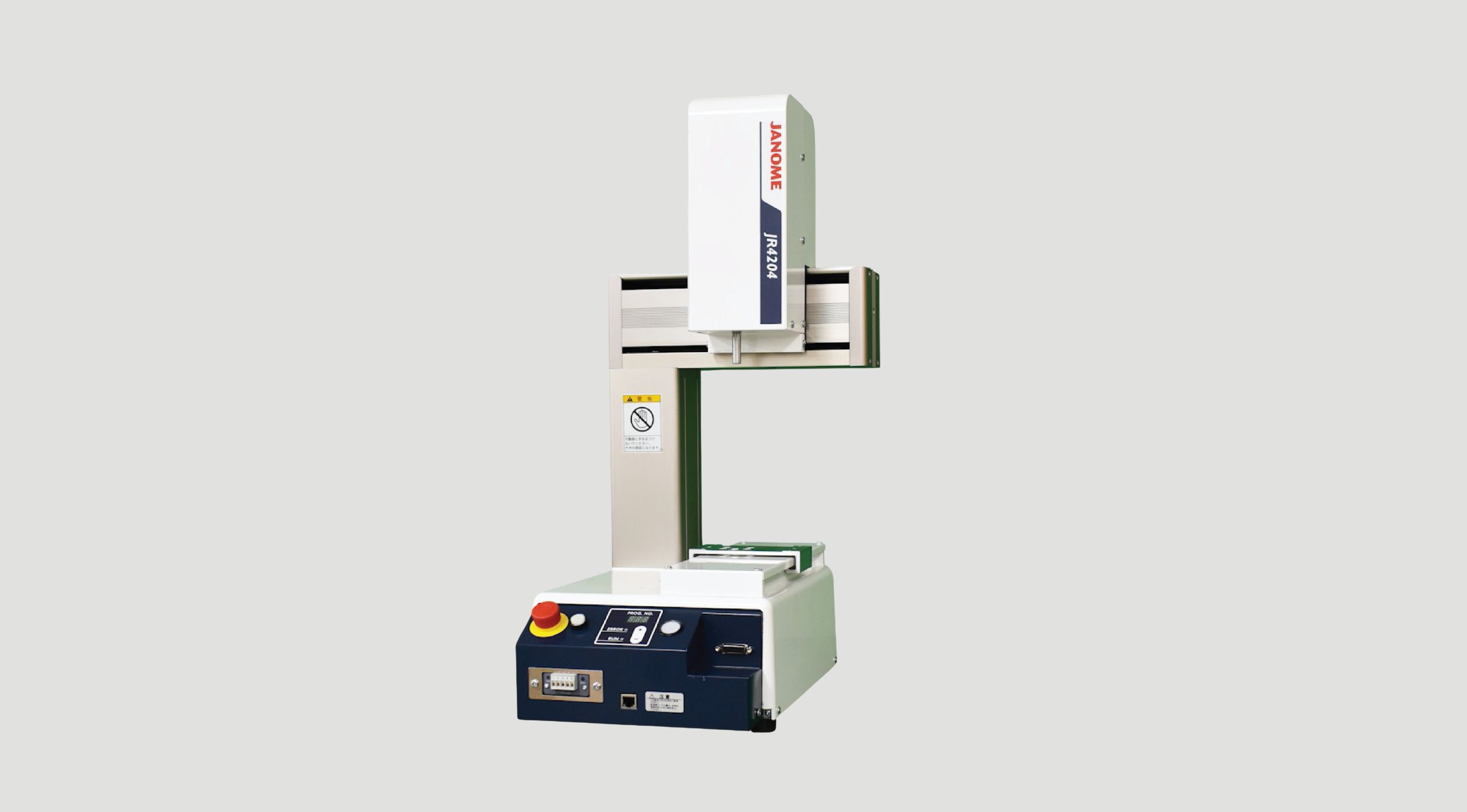
New flagship desktop model from Janome
Model: JR4203, JR4204, JR4303, JR4304, JR4403, JR4404, JR4503, JR4504, JR4603, JR4604
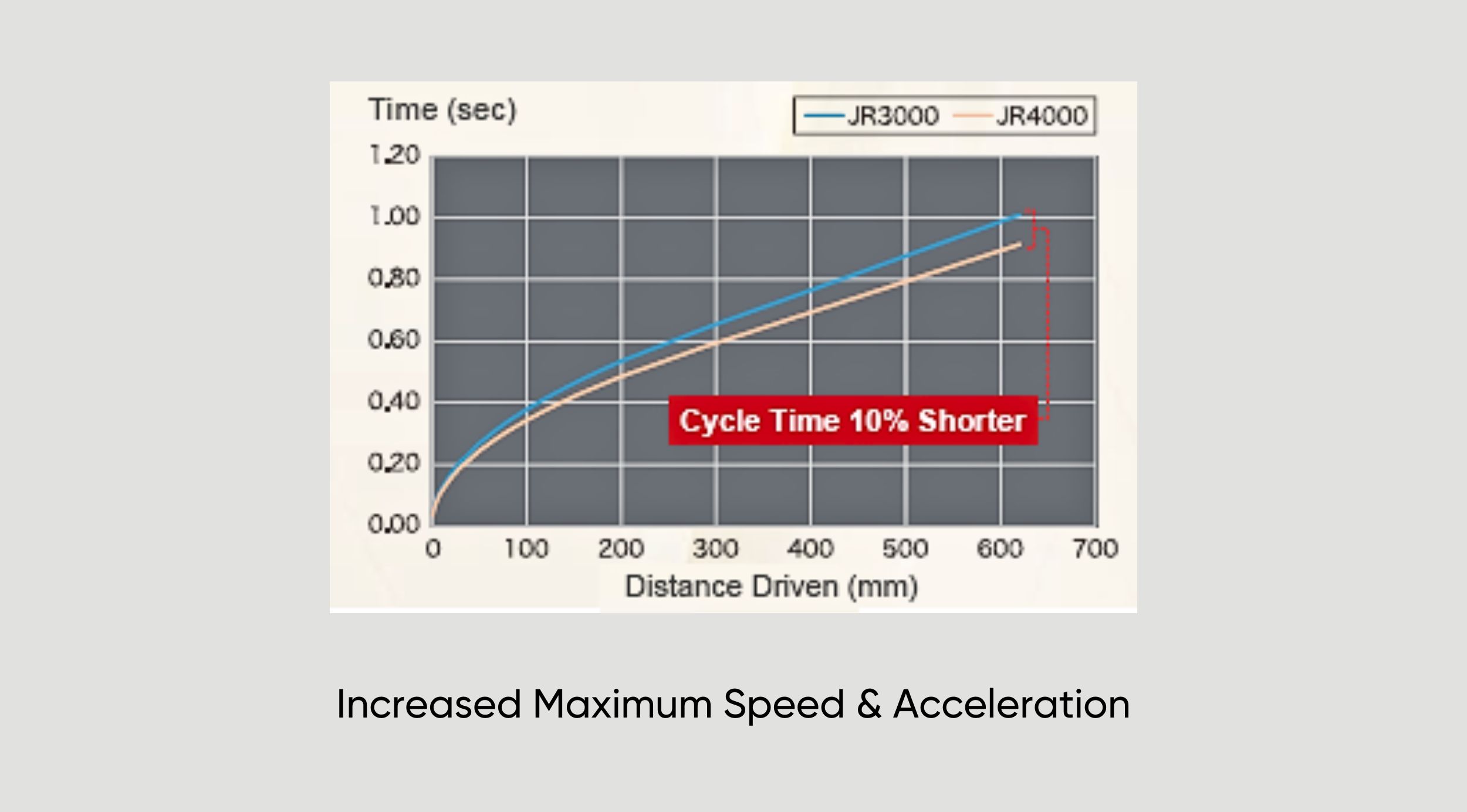
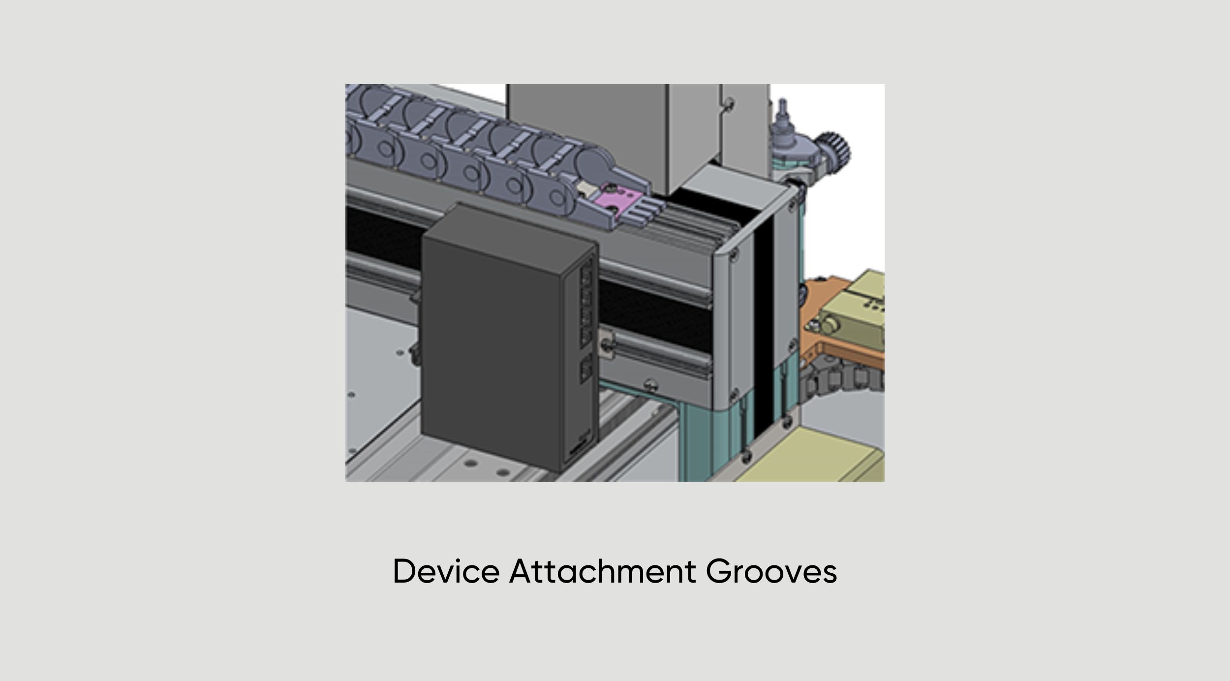
The top and rear of the Y Axis arm feature grooves for attaching external devices.
Easily consolidate wiring when attaching external tools, etc.
In addition to the conventional Safety Category 1, Performance Level PL=c circuit, it is possible to select the option of constructing an external Safety Category 3, Performance Level PL=d safety circuit (with a motor power supply turn OFF) for dangerous jobs and/or facilities.
Connect up to 2 "pulse string input type" devices, such as stepping motors or servomotors.
2 control modes and an encoder input function for compatibility with a variety of applications.
- Point Mode: The auxiliary axes move in tandem with the robot's X, Y, Z and R Axes.
Example: a 4 Axes dispensing robot expands to 6 axes.
2 axes are added to change both the syringe angle and the workpiece angle to set the angles for dispensing on the outer edge surface of a hole cut into a tubular workpiece.- Independent Mode: The auxiliary axes move independent of the robot's X, Y, Z and R Axes.
Example: Have the robot do a job while running a conveyor.
The auxiliary axis (or axes) operate independent of the point coordinates and movements, allowing the robot to execute jobs such as dispensing or screw tightening while the conveyor runs.- Encoder Input: Acquire external encoder values and monitor the rotation amount; also control sensors.
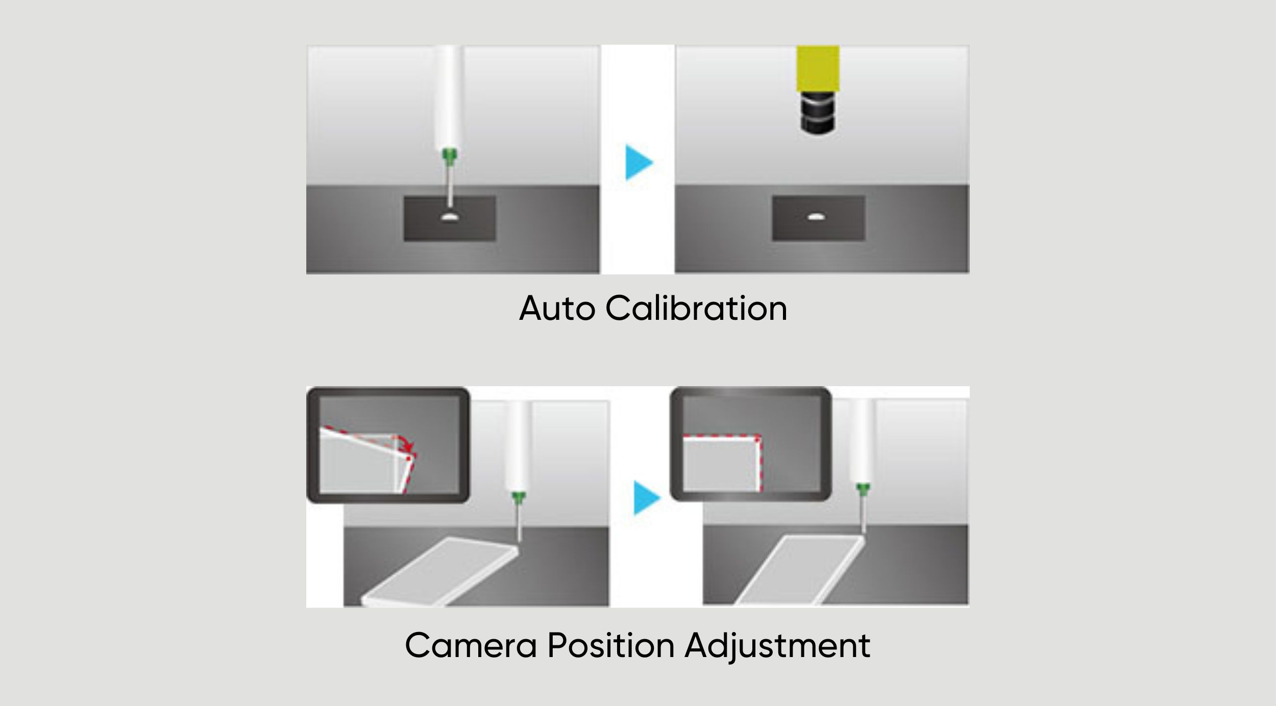
With an optional AS200 position adjustment camera, make position corrections for displaced workpieces for accurate jobs.
No need for specialized camera software; both the robot and the camera are settable with our original "JR C-Points III" software.
Auto Calibration
Camera Position Adjustment
In addition to the signal control and point job-based data exchange functions from our previous model, we added a "Fieldbus Register Output Function" to the JR4000 for constant output of specified types of data, which allows the user to consistently acquire necessary data from a PLC with making complicated settings.
Freely program the robot with point jobs, even with jobs for which there are no preset point types.
Compared with our previous model, the JR4000 offers more usable commands and built-in variables and expanded function customization capabilities.
*Other features such as user-friendly teaching, needle adjuster functions, etc., are carried over from the JR3000 Series.
Janome's original PC software "JR C-Points III" is a comprehensive interactive program input system allowing users to create, edit and save teaching data and customizing data all on their PC.
Show movement point coordinates graphically to instinctively grasp program content, as well as convert coordinates from CAD data. Setting parameters are also shown in the convenient tree view for confirmation and editing.
Convert "JR C-Points II" teaching data into "JR C-Points III" data for use with the JR4000.
- Ribbon Control
Click each category tab and the function buttons and setting items for that tab appear.- Graphic Editing View
Teach visually with the 3D view in the 3D display graphic editing area.- Point Data Editing View
Directly edit the selected point data elements, including the point type, coordinate positions, point job, etc.- JOG View
Connect to the JR4000 Robot and make JOG movements directly from a PC.
Greatly Enhanced Point Graphic Functions
3DCAD Upload Capability
Referring to uploaded 3DCAD data, automatically generate teaching points, and greatly reduce your teaching burden.
A new point type, "Spline Curve Drive" is built into the system program, making it possible to handle even workpieces with difficult shapes.
Easily Adjust Registered Point Coordinates
Easily offset, enlarge or reduce the coordinate image on the graphic display.
Adjust the coordinates to match the actual robot for easy operation.
Quick Guide
Select a menu item or function and the "Quick Guide" shows an explanation of that selection on the PC software display. There is no need to take out the operation manual just to confirm the content of a given function.
Tablet PC Compatibility
Change user interfaces between a standard PC and a tablet PC.
Operate the robot comfortably even in different environments.
*For safety, use a Safety Commander© when using a tablet PC.
*Safety Commander© is a trademark and/or registered trademark of IDEC CORPORATION.
Coordinate Conversion Function for Workpiece Variation Adjustment
Converts the job coordinates to match the coordinates for each individual workpiece written to the software to compensate for individual variations when doing the same job on multiple workpieces. Horizontal deployment is more efficient as the additional effort for making fine adjustments is eliminated.
Operation Lock Function
Set a password from a Windows account with administrator rights, and lock the data so it cannot be saved or overwritten from other accounts.
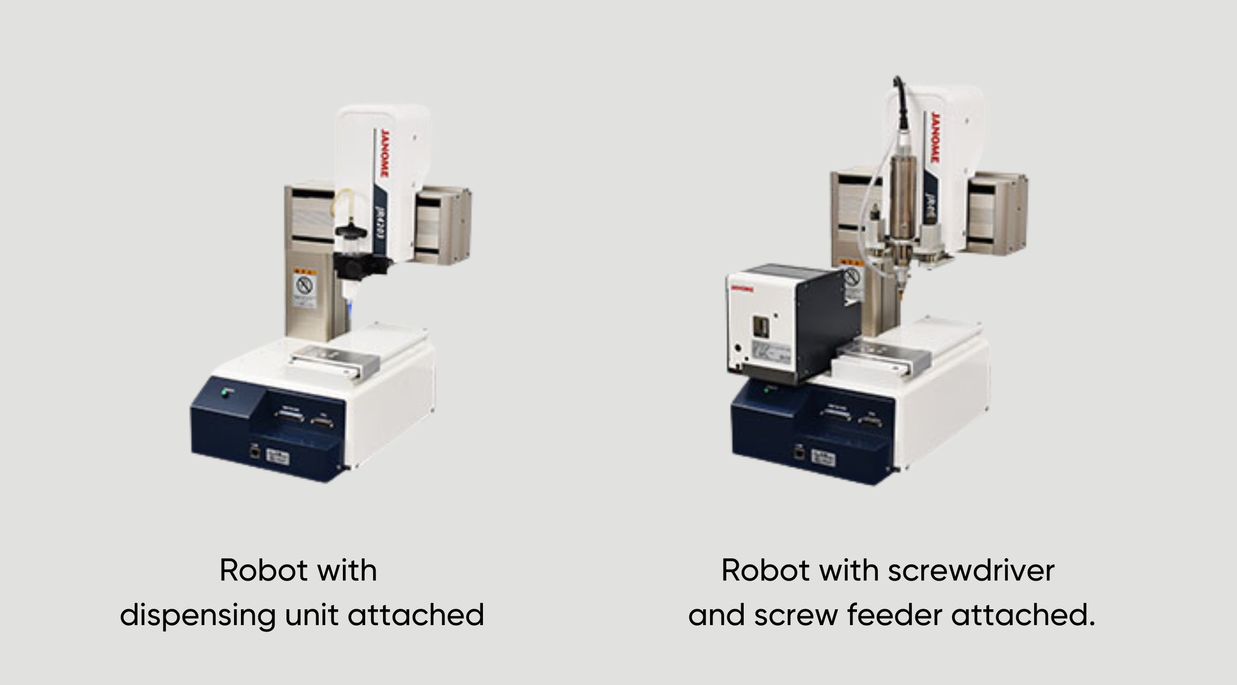
Dedicated software for screw tightening and dispensing jobs.
Robot with screwdriver and Janome screw presenter attached
Creating screw tightening job programs is easy: just set the job positions for screw tightening parameters such as screw pitch, length, and the driver rpm.
Robot with dispensing unit attached
Creating dispensing programs is easy: just set the job positions for dispensing parameters such as point dispensing or line dispensing.
| JR4203 | JR4303 | JR4403 | JR4503 | JR4603 | ||
|---|---|---|---|---|---|---|
| Operating Range | X・Y Axes | 200x200mm | 300x320mm | 400x400mm | 510x510mm | 510x620mm |
| Z Axes | 50mm | 100mm | 150mm | |||
| Maximum Portable Load |
Workpiece | 7kg | 15kg | |||
| Tool | 3.5kg | 7kg | ||||
| Maximum Speed *1 <PTP Movement> ( )=setting range |
X - Y Axes | 700mm/s (7~700) |
1000mm/s (10~1000) |
|||
| Z Axes | 250mm/s (2.5~250) |
400mm/s (4~400) |
||||
| Maximum Speed *1 <CP Movement> =setting range |
X-Y-Z Combined Speed |
600mm/s (0.1~600) |
850mm/s (0.1~850) |
|||
| Repeatability *2 | X Axes | ±0.006mm | ±0.007mm | ±0.008mm | ±0.008mm | |
| Y Axes | ±0.01mm | |||||
| Z Axes | ±0.008mm | |||||
| External Dimensions*3 ( )=Double Column Type |
W×D×H *excluding protrusions |
323 x 389 x 554mm |
560 x 535 x 659mm | 584 x 630 x 807 mm (615 x 631 x 807) |
678 x 730 x 807mm | 790 x 730 x 807mm |
| Main Unit Weight*3 ( )=Double Column Type |
20kg | 36kg | 42kg (45) |
45kg | 46kg | |
| JR4204 | JR4304 | JR4404 | JR4504 | JR4604 | ||
|---|---|---|---|---|---|---|
| Operating Range | X x Y Axes | 200×200mm | 300×320mm | 400×400mm | 510×510mm | 510×620mm |
| Z Axes | 50mm | 100mm | 150mm | |||
| R Axes | ±360° | |||||
| Maximum Portable Load | Workpiece | 7kg | 15kg | |||
| Tool | 3.5kg | 7kg | ||||
| Maximum Speed*1 <PTP Movement> ( )=setting range |
X - Y Axes | 700mm/s (7~700) |
1000mm/s (10~1000) |
|||
| Z Axes | 250mm/s (2.5~250) |
400mm/s (4~400) |
||||
| R Axes | 600°/s (6~600) |
900°/s (9~900) |
||||
| Maximum Speed*1 <CP Movement> ( )=setting range |
X - Y - Z Combined Speed |
600mm/s (0.1~600) |
850mm/s (0.1~850) |
|||
| Acceptable Moment of Inertia | 65kg - cm² | 90kg - cm² | ||||
| Repeatability *2 | X Axes | ±0.006mm | ±0.007mm | ±0.008mm | ||
| Y Axes | ±0.01mm | |||||
| Z Axes | ±0.01mm | |||||
| R Axes | ±0.008° | |||||
| External Dimensions*3 ( )=Double Column Type |
W×D×H *excluding protrusions |
323 x 389 x 676mm | 560 x 535 x 844mm | 584 x 630 x 894mm (615 x 630 x 894) |
678 x 730 x 894mm | 790 x 730 x 894mm |
| Main Unit Weight*3 ( )=Double Column Type |
22kg | 39kg | 46kg (49) |
49kg | 50kg | |
*1 Maximum speed can vary depending upon conditions. The robot cannot reach maximum speed when bearing the maximum portable load.
*2 Position repeatability is not a guarantee of absolute precision.
*3 With optional specifications, the external dimensions and the robot's mass may change. Please contact us for details.
| Drive Method | 5 phase pulse motor drive (encoder added as an option) | |
|---|---|---|
| Control Method | TP (Point to Point) control, CP (Continuous Path) control | |
| Interpolation | 3-dimensional linear, 3-dimensional arc interpolation and spline curve interpolation | |
| Teaching System | Remote teaching (JOG) / Manual Data Input (MDI) | |
| Teaching Method |
|
|
| Screen Display Languages | Japanese, English, French, Spanish, Italian, German, Korean, Simplified Chinese, Traditional Chinese, Czech, Vietnamese | |
| Program Capacity | 999 programs | |
| Data Capacity | Up to 32,000 Points | |
| Simple PLC Function | Up to 100 programs, with up to 1,000 steps/program | |
| External Input/Output | I/O-SYS (optional) |
16 inputs, 16 Outputs |
| I/O-1 (optional) |
16 inputs, 14 Outputs (including 2 relay outputs) | |
| I/O-S (optional) |
Interlock connector for an area sensor, etc.
|
|
| I/O-MT (optional) |
For auxiliary axes (pulse string input type)control; control up to 2 axes |
|
| Field Network (optional) |
CC-Link, EtherNet/IP, PROFINET | |
| COM1(optional) | RS-232C for external device control, COM commands | |
| COM2, COM3 (optional) |
RS-232C for external device control | |
| LAN |
Ethernet connector for PC
|
|
| ENC-IN (optional) |
For external encoder value input | |
| TPU | Dedicated teaching pendant connector (optional) | |
| SWITCHBOX | Dedicated switchbox connector | |
| I/O Built-in Power Supply(optional) | 24V Rated 2.1A | |
| Power Source | AC100-120V/200-240V (Single Phase) 50/60Hz | |
| Power Consumption | 200W | |
| Operating Enviroment | Temperature | 0~40°C |
| Relative Humidity | 20~90% (Without condensation) | |
| Standard Accessories | Power Cable |
|